Object positioning in the network
|
The RailTopoModel® data structure is organized around the network. The Network is used as the main reference system for positioning of arbitrary information objects. This layer allows the user to project objects and entities on the topology, by referencing topology elements.
- The network is built of NetElements
- Objects like infrastructure assets can be located on the network as NetEntities
Net Entities and Entity Locations
To define all types of entity, a generic class is defined: NetEntity. This class defines a general relation with a shared location to define the position on the network. The location of each entity on the network is defined using the intrinsic position of NetElement. NetEntities, specialised as LocatedNetEntities, are located by assigning EntityLocations to them. An EntityLocation connects an Entity to the Network via one or more PositioningNetElements.
The figure below shows different examples of infrastructure assets that are located in the railway topology network as net entities.
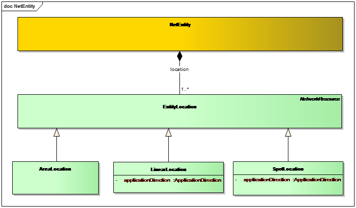
Each NetEntity instance possesses an unspecified number of EntityLocation instances. Each EntityLocation instance is specialised as one of three types used to locate different types of NetEntities on the network:
- SpotLocation: used for information objects happening at a point (e.g.: signals, buffer stops, ETCS balise, etc. - see number 1 in previous example)
- LinearLocation: used for information objects happening along a path (e.g.: platform, speed limit, ballast renewal, etc. - see number 2 in previous example)
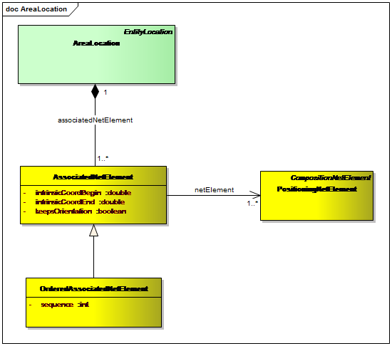
- AreaLocation: used for information objects happening on a sub network (e.g.: catenary cases, track circuits zones, switches, stations, tunnels, bridges, etc. - see number 3 in previous example)
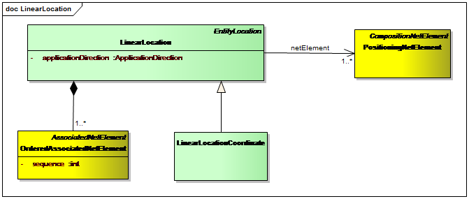
The following figure shows the RailTopoModel® class model for net entity locations.
A NetEntity can have more than one EntityLocation in the Network. Consider the following examples:
- An object can be located in the railway network via a positioning system, and additionally via an intrinsic positioning. See later explanations
- A level crossing of two tracks is located on each of those tracks by (at least) one SpotLocation.
- A switch has an AreaLocation (see picture), but can as well be located at its branching point by a SpotLocation
- A station on the micro level of the network is represented by an AreaLocation. On the macro level it is condensed as operational point to a single topological node (nonlinear NetElement) and therefore is assigned a SpotLocation.
The last two examples show that a consequent classification of NetEntities into three types, Spot Entity, Linear Entity and Areal Entity is not always possible.
Relating EntityLocations to the Network
The three types of EntityLocations are related in different ways to the network. Using an AreaLocation instance for connecting to the network means that the "NetEntity" in question is related to a subset of "NetElement" instances which together resemble an area or a sub-network.
A connection based on a LinearLocation instance means that the "NetEntity" in question is a path related to a linear segment of the network.
A connection based on a SpotLocation means that the "NetEntity" in question is either related to a nonlinear NetElement building block of the network or it is related to a specified position on a linear NetElement.
| Note that - with reference to NetElements - the terms linear or nonlinear are used for illustration only. In the RailTopoModel® network, there are only NetElements and Relations. You can imagine a nonlinear NetElement as a "node" and a linear NetElement as an "edge" to get a better understanding, but it will make no difference in the topology or the positioning of NetEntities. |
SpotLocation
An entity can be located via a SpotLocation either at a nonlinear element or along a section of rail/section of line (linear element) at a certain distance.
If it is located at a nonlinear element, it can be interpreted as happening "in" the element (regardless the orientation). In this case, it encompasses the whole nonlinear element. Otherwise, it happens with respect to some relation of the nonlinear element (exit or entry via another net element, for example from an adjacent track edge X). It should then be located using a SpotLocation on the adjacent linear net element.
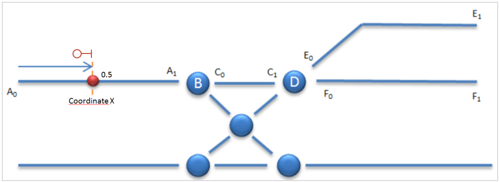
The following figure shows an example where a signal is located in the center of the linear net element A via a SpotLocation.
If a NetEntity is situated somewhere along a track edge (linear net element) at a certain distance from the start, it is further necessary to define the lateral offset and the application direction. In particular, it has to be clarified whether the entity happens directly on the track edge, or somewhere left or right of the track edge with respect to its orientation; and if the entity occurs in both directions or only in one. For example: a conventional railway signal is located either left of right of (or above) the track and it is valid for only one direction of travel.
Further, it is possible to have more than one SpotLocation for some spot entities:
- Multiple location (on multi-track) on the network for the same hierarchical level (micro, macro, etc.).
- Multiple location, because the entity is located on different levels.
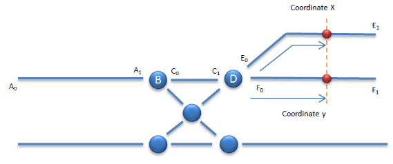
The following example may show the location of a clearing post. While the position of the clearing post is somewhere in the middle between the two tracks (not depicted), its application points exist on both tracks (linear elements E and F) that are going to join in the nonlinear net element D. Thus, the clearing post element has two spot locations on the same hierarchical level.
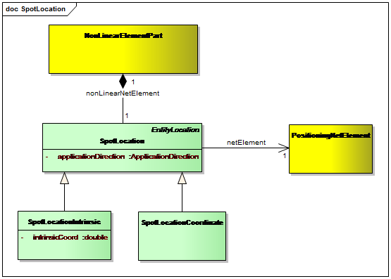
In terms of RailTopoModel®, a SpotLocation is related to exactly one PositioningNetElement, which could be either nonlinear or linear. This means that the NetEntity in question is located on this NetElement and its applicationDirection refers to the NetElement’s orientation. The exact localization of the SpotLocation is given depending which of two types it belongs to:
SpotLocationCoordinate
A SpotLocation of this type is related to a PositioningSystemCoordinate that refers to a specific PositioningSystem. This is either a LinearPositioningSystem or a GeometricPositioningSystem. The PositioningSystemCoordinate provides the exact position of the SpotLocation in the referenced coordinate system.
SpotLocationIntrinsic
A SpotLocationIntrinsic carries the intrinsicCoordinate in reference to the chosen PositioningNetElement, as a value between 0 and 1.
In the spot location example from the begin of the chapter, we see a SpotLocation for a railway signal on linear NetElement A. The applicationDirection in this case is "reverse", since the signal is valid in direction 1 to 0 on A. The NetEntity of the signal "happens" at a certain distance left from the endpoint A1. As a SpotLocationIntrinsic its intrinsicCoord is 0.5. As a SpotLocationCoordinate its external coordinate is X in a referenced positioning system.
LinearLocation
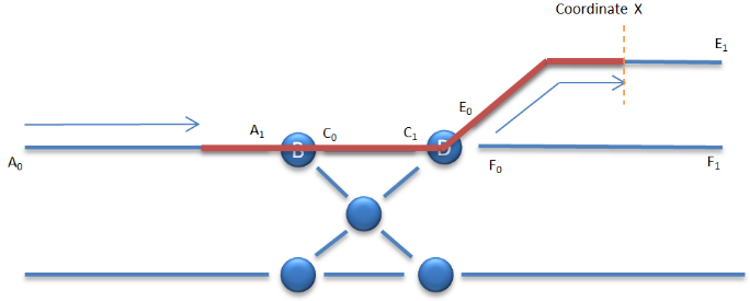
Many NetEntity instances can be seen as paths. For example, a platform edge is a linear infrastructure asset, and also track circuits or axle-counting circuits can be seen as linear installations in the railway track network. The following figure may show the axle-counting circuit example.
To describe a path or linear location, a start point, an end point and an ordered list of every encompassed element, is needed.
The start and end points are point locations, thus either a nonlinear element or a point along a linear element (track edge). The path should be a topological path, meaning that at each nonlinear element only one exit direction can be taken. If the start- or end point is a nonlinear element, this element is fully encompassed within the path.
The correct ordering of the list should be checked against the topology definition of the network. This could be the task of a validator. The orientation of the path on each track edge can be deduced from the order of the crossed nonlinear elements.
Path locations in RailTopoModel® are located by instances of the class type LinearLocation.
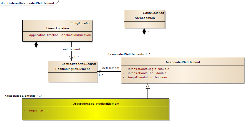
A LinearLocation is defined by an ordered sequence of AssociatedNetElements. Each AssociatedNetElement refers to a linear or nonlinear PositioningNetElement. It either encompasses the whole NetElement or a section at the beginning or end of the linear NetElement (or an arbitrary section in case there is only one AssociatedNetElement)
The beginning and end of the sections of AssociatedNetElements are given in intrinsic coordinates (between 0 and 1) with respect to the related PositioningNetElement. The parameter keepsOrientation defines if the AssociatedNetElement is oriented along the direction of the NetElement or in reverse direction.
The AssociatedNetElements have to be oriented all in the same direction, from the start to the end of the sequence. They form a connected path in the network without gaps or branches.
The position of the LinearLocation instance within the network itself is now complete. Additionally, more positioning systems can be used for the respective entity. If the LinearLocation is a LinearLocationCoordinate, it can be assigned a position with respect to an external – linear or geometric – PositioningSystem.
The following figure shows how the intrinsic coordinates are used to reference begin and end coordinates of the linear element.
In particular, the example shows the LinearLocation and its AssociateNetElements with respect to the underlying NetElements. When writing this sequence as ordered list of NetElement segments, the results looks as follows:
| Nr | AssociatedNetElement | netElement | intrinsicCoordBegin | intrinsicCoordEnd | keepsOrientation |
|---|---|---|---|---|---|
| 1 | A' | A | 0.7 | 1 | true |
| 2 | B' | B | 0 | 0 | n/a (nonlinear) |
| 3 | C' | C | 0 | 1 | true |
| 4 | D' | D | 0 | 0 | n/a (nonlinear) |
| 5 | E' | E | 0 | 0.8 | true |
Remark: In this example, all the underlying linear NetElements are oriented in the same direction, as can be seen by the positions of their intrinsic coordinates 0 and 1. In case that a linear NetElement instance, say E, were oriented in the other direction, the AssociatedNetElement instance E’ would have to be defined by intrinsicCoordBegin = 0.2, intrinsicCoordEnd = 1 and keepsOrientation = false.
AreaLocation (SubNetwork)
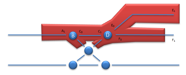
An area location can be seen as aggregated location that comprises spot locations and several linear locations in an unordered sequence. The example shown in the following figure may be a more realistic representation of an axle-counting circuit.
An areal object is an object represented by a subgraph (a continuous fraction of the network), that is comprehended as an object. The name "areal object" indicates that most practical examples resemble an area in reality. The respective AreaLocation is this subgraph or sub-network. Another example for an area location is the track network belonging to a station or a shunting yard.
An AreaLocation is defined analogously to spot- and linear entity locations, by listing the AssociatedNetElement instances of the location, with a pair of positions (beginning and end in intrinsic reference on the respective PositioningNetElement instance) for all AssociatedNetElements.
The difference to LinearLocation is that the set of AssociatedNetElements does not have to be ordered and can have different orientations. Further there can be branches within the subgraph
As in the case of LinearLocations, if a nonlinear element is included in the collection of AssociatedNetElements, then the whole element is included. The collection can include sections of linear elements, defined by their intrinsic begin and end coordinate. It must be checked that the objects included in the areal location form a connected subgraph (no independent parts) and that no object is listed twice.
The AreaLocation in the example contains 8 AssociatedNetElement instances. Note that element E is fully included in E’, but not the adjacent nonlinear NetElement (node) in the network. The track edges A and G are oriented reverse to each other, which does not matter in an AreaLocation.
| What you should have learned | |||
|---|---|---|---|
| Please, enter a summary! | |||
| Navigation | |||
| Home | ← | • | → |
| Chapter | RailTopoModel® Quick Start | RailTopoModel® Modelling Concepts | RailTopoModel® External References |
| Section | Positioning | Object positioning in the network | |
| Subection | |||

